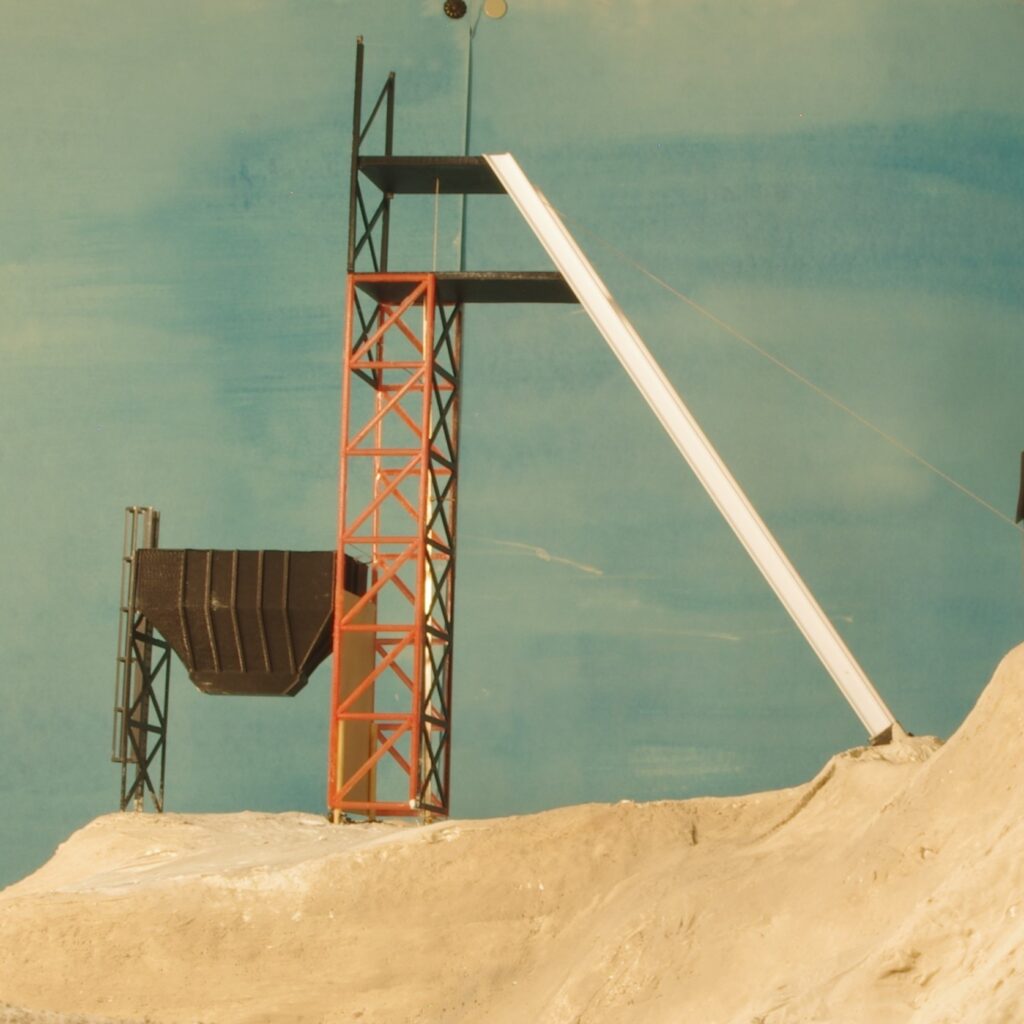
On a hill near Shafter, Texas (a former silver mining town) is a steel headframe built to carry material from the mine deep underground. A building nearby presumably houses the hoist.
This setup is modeled on my model railroad. The working hoist (powered by an electric motor) is inside the uncompleted building at the right of the image. The headframe, secured by two white-colored plastic I-beam components provides structural support as the “cable” (thread, in my case) tugs a skip from the mine. In underground mining, a skip is a device which carries material up a shaft and out of the mine.
Most of the components were designed in Autodesk’s Fusion 360 program and 3-D printed, although some came from other sources.
Creating the Headframe
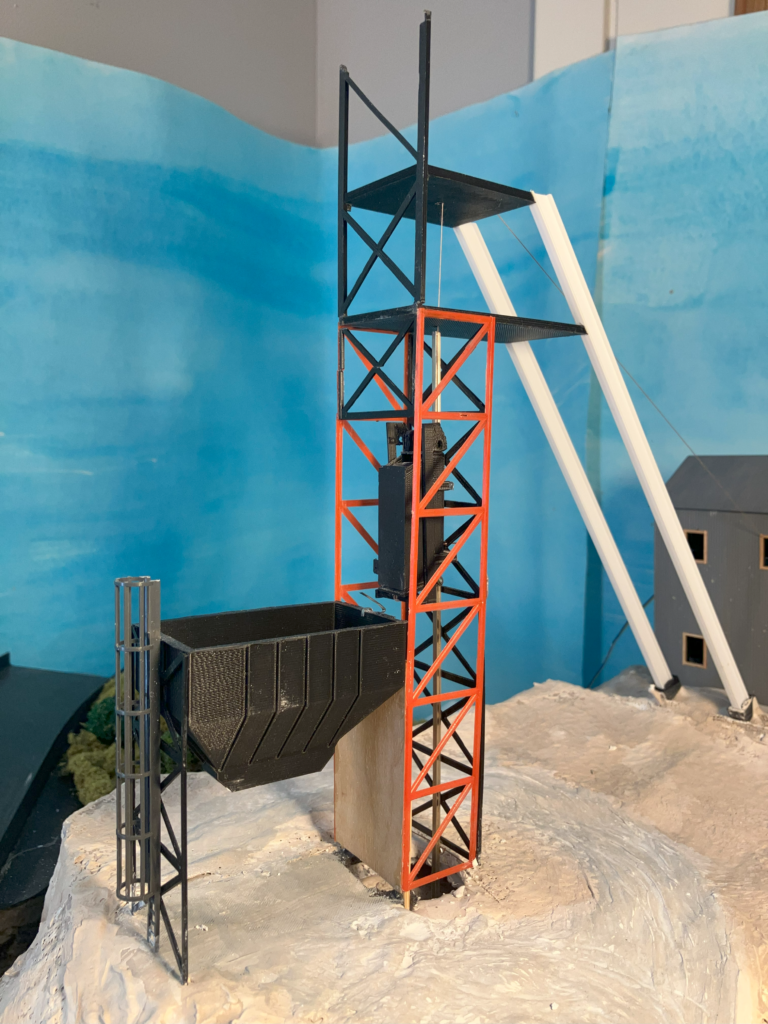
The more square-shaped truss pieces (orange colored) were purchased from Plastruct, while the black-colored ones were 3-D printed. The white I-beam components (white colored) are also from Plastruct, as is cage ladder (in dark grey plastic). The ore bin (black colored) is 3-D printed.
Creating the Hoist Mechanism
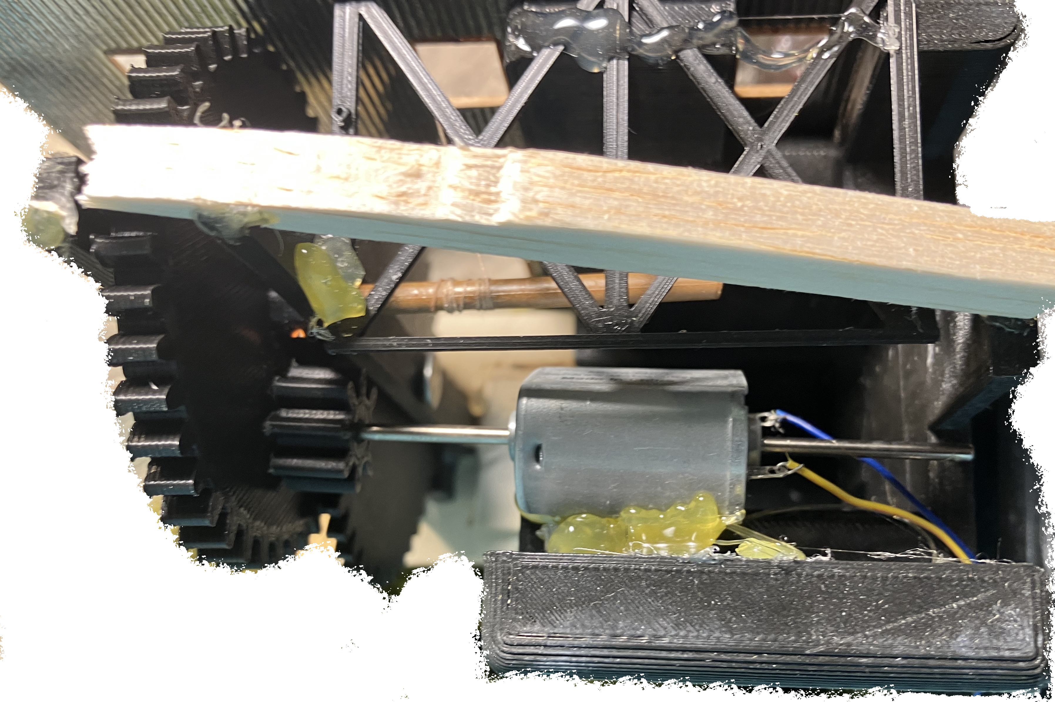
All gears in the hoist mechanism are 3-D printed, as are the components that support them. The winder (brown colored and toward the center of the image) is a piece of plastic I had on hand. The motor, a better quality low-speed quiet motor, came from Micro Mark.
The speed-reduction gears allow the winder to turn very slowly, even if the motor is turning much faster, creating an impressively slow hoist minimum speed. The torque generated by these speed-reducing gears is also impressive.
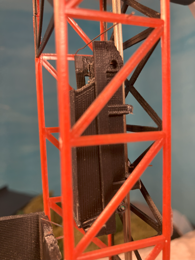
The Guiding Rail
To guide the skip as it moves up and down, a piece of model railroad rail runs parallel to the headframe trusses. It is secured at the top and bottom and can be removed if necessary to make repairs.
Creating an Operating Skip
The skip was among the more complex parts of this project. By design, it moves up the headframe, tips into a dumping position, and returns to a vertical position before moving back down the headframe, all with only the tension of the thread. It is nearly completely 3-D printed, with the exception of a wire spring, metal rail joiners (to hold the assembly against the guiding rail), and a wire piece (used as a hinge pin). How does it work? I have attempted to explain below:
Moving Up the Headframe
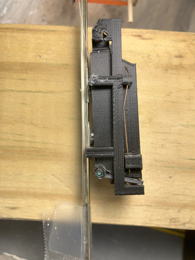
As the thread tugs the skip upward, the assembly approaches a nearly-invisible wire (visible at left). Note (at right) the 3-D printed brackets which allow the skip bucket to move independently, while sliding along the metal rail. The skip bucket is held along this bracket assembly by a magnet and a formed wire spring (at right).
Moving into a Dumping Position

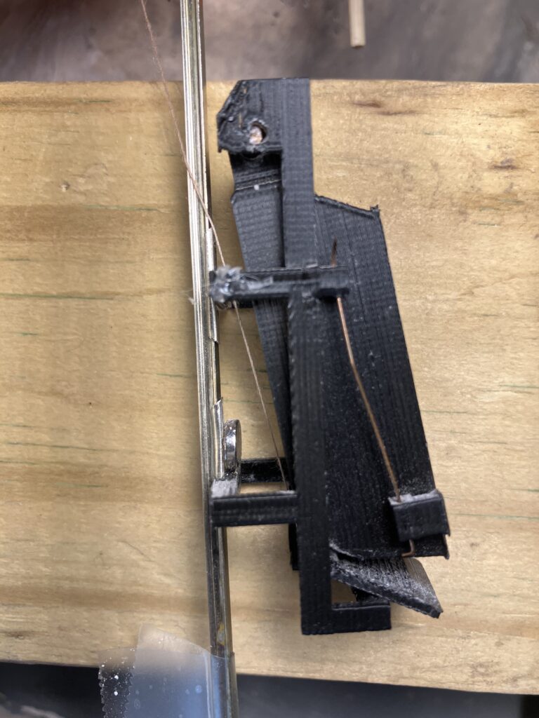
As the bracket assembly presses against the wire (at left), the hoist is still winding in the thread. The thread is wrapped such that as tension increases, the skip bucket is pushed outward. This force overcomes the tug from the magnet and a formed metal wire spring. This system replicates the appearance of an actual mine skip dumping, but does not replicate the mechanical processes used.
Folding Back into a Vertical Position
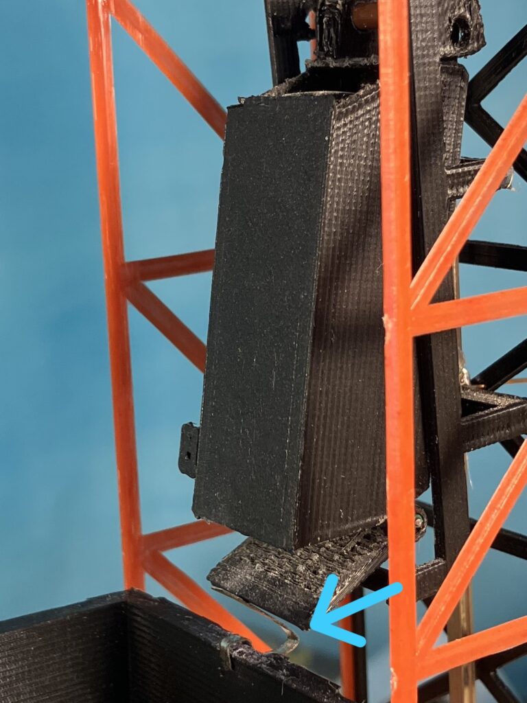
When the power is reversed, the hoist begins winding out thread, and the skip assembly moves down the headframe due to its weight. A small, nearly-invisible metal piece (located at the top of the ore bin, on left image) forces the skip bucket back into a vertical position as it drops. Only the headframe is visible once the assembly moves completely “underground” (at right).
Reflections
This project was very complex, and it has required occasional maintenance. However, this has not proved too complex.
I do not actually consider this project finished; I still need to add paint, some additional truss pieces between the white-colored I-beam supports, and other details. For now, though, I have moved onto other projects.